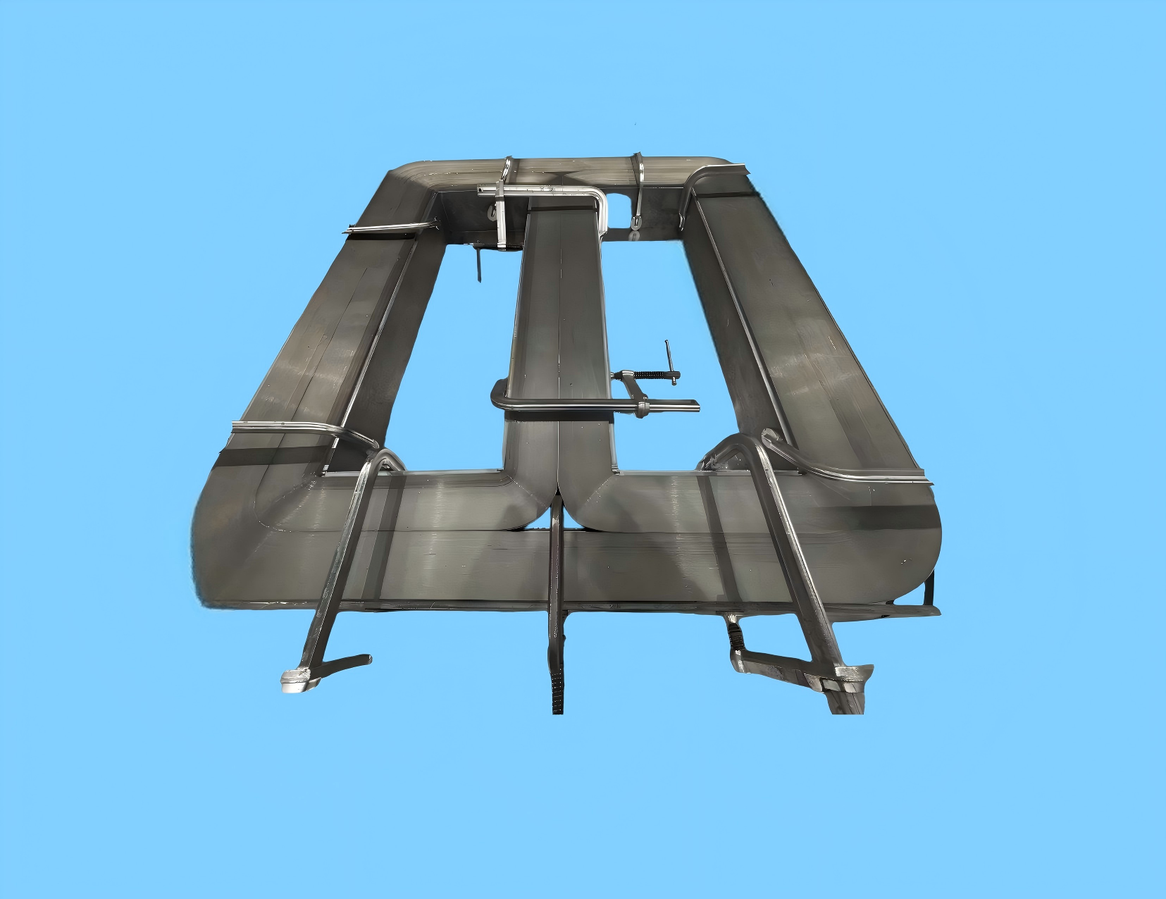
The MagComponent amorphous planar core (AMDT series) is a flat distribution-transformer core wound from 1K101/1K102 iron-based amorphous ribbon. It is the geometry behind the SCBH15/19 dry-type sizes and the oil-immersed range published on this page. No-load loss is stated as 60–80% lower than traditional silicon steel transformers. Saturation flux density is 1.56 T, and core loss is below 0.15 W/kg at 50 Hz, 1.35 T.
| Parameter | Value | Unit | Test Conditions |
|---|---|---|---|
| Saturation Flux Density (Bs) | 1.56 | T | H = 800 A/m |
| Coercivity (Hc) | < 4 | A/m | - |
| Curie Temperature (Tc) | 415 | °C | - |
| Resistivity (ρ) | 130 | μΩ·cm | Room Temperature |
| Ribbon Thickness | 0.025 | mm | - |
| Core Loss (Pcv) | < 0.15 | W/kg | @ 50Hz, 1.35T |
These rows are the line-frequency set published for this amorphous planar core. Core loss is stated at 50 Hz and 1.35 T. Coercivity is below 4 A/m, ribbon thickness is 0.025 mm, long-term operation is stated at 130°C, and Curie temperature is 415°C. The amorphous E-core page publishes a different loss point for the same 1.56 T alloy family: 20–50 W/kg at 20 kHz and 0.2 T, with Curie temperature stated there as 410°C. Use the 50 Hz row on this page for distribution-transformer designs, and the 20 kHz row only when the part is an E-core.
| Rated Capacity (kVA) | External Dimensions (A1×B1/mm) | Window Dimensions (A2×B2/mm) | Core Height (D/mm) |
|---|---|---|---|
| 30 | 474 × 538 | 285 × 140 | 142 |
| 100 | 572 × 674 | 380 × 205 | 213 |
| 400 | 1030 × 1030 | 500 × 245 | 284 |
| 1000 | 1454 × 1266 | 1000 × 309 | 284 |
| 2000 | 1618 × 1516 | 2000 × 374 | 426 |
30 kVA to 1600 kVA. This range is published for oil-immersed cores only. Dry-type SCBH15/19 examples in the table above run from 30 kVA to 2000 kVA, with window and height listed for each step.
Choose this planar core when the magnetic circuit is a distribution transformer evaluated at line frequency, and the catalog window in the SCBH15/19 table fits the winding. The loss number that applies is the one on this page: below 0.15 W/kg at 50 Hz and 1.35 T. The ribbon is the same 1K101 amorphous ribbon family used for silicon-steel replacement in distribution transformers, where that page publishes core loss of 0.1–0.14 W/kg at 1.35 T / 50 Hz and a 60–80% no-load loss reduction.
| Selection point | Amorphous planar core (this page) | Amorphous E-core | Amorphous 3D triangular core |
|---|---|---|---|
| Shape | Flat core with a rectangular window for SCBH15/19 dry-type and oil-immersed transformers | Open E for bobbin winding and a cut air gap | Three-phase wound core with equal magnetic path lengths |
| Published loss point | < 0.15 W/kg at 50 Hz, 1.35 T | 20–50 W/kg at 20 kHz, 0.2 T | < 0.15 W/kg at 50 Hz, 1.35 T, as published on the 3D triangular core page |
| Capacity published on that page | Dry-type examples 30–2000 kVA; oil-immersed 30–1600 kVA | JHAE series for converters and inductors, not a kVA distribution table | 100–2000 kVA |
| Saturation flux density | 1.56 T | 1.56 T | 1.56–1.61 T |
| Use it when | The specification is a planar distribution transformer at 50 Hz and one of the published window sizes | The winding is a bobbin on an E, and the relevant loss point is 20 kHz | Three-phase magnetic symmetry is the reason for the core, inside 100–2000 kVA |
Figures in the E-core and 3D columns are the values already published on those MagComponent pages. They are not new measurements for the planar core.
An amorphous E-core is the part to quote when the design is a gapped inductor or a medium-frequency transformer that will be wound on a bobbin. Its published core loss is at 20 kHz, not at 50 Hz. The planar core does not offer that cut-gap E geometry.
The amorphous 3D triangular core uses the same loss class (below 0.15 W/kg, 60–80% versus silicon steel) but is specified for three-phase symmetry from 100 kVA to 2000 kVA. Stay with the planar core when the drawing is a flat SCBH window, including the 30 kVA step that the 3D range does not list.
A nanocrystalline C-core is a cut core in a different alloy: saturation 1.2 T, Curie temperature 570°C, and ribbon thinner than 26 μm on that page. It is aimed at high-frequency transformers and inductors, not at the 50 Hz planar distribution sizes above.
The published duty is line-frequency distribution and the infrastructure loads that sit on those transformers. For grid and inverter context see renewable energy and smart grid, for traction substations see rail transportation, and for UPS and data-hall distribution see AI data centers. A related design discussion of transformer size and efficiency is in solid-state transformers and the green-energy case.
SCBH15/19 dry-type and oil-immersed replacements where the buying specification is no-load loss at 50 Hz. The dry-type table lists 30, 100, 400, 1000, and 2000 kVA.
Step-up and station transformers for wind, photovoltaic, and storage sites that still use a line-frequency planar core. Inverter magnetics at 20 kHz belong on the E-core page, not here.
Substation and auxiliary distribution transformers for rail, airports, and highways, using the oil-immersed range of 30–1600 kVA or a dry-type window from the SCBH table.
Facility transformers and UPS distribution where the core runs at line frequency and the published advantage is the 60–80% no-load loss reduction versus silicon steel.
Onboard chargers and DC-DC converters need a gapped E-core or a low-permeability nanocrystalline ribbon. This planar core is the distribution transformer that feeds a site, not the vehicle power stage.
Factory distribution transformers in the published kVA steps. Variable-frequency drive reactors, which are inductor shapes, are covered by the amorphous E-core instead.
Advanced research and development facilities with continuous innovation
Strict quality control processes ensuring product consistency and reliability
Products meet international environmental and energy efficiency standards
We can customize AMDT cores according to your specific drawing requirements
Tailored magnetic properties to meet unique application needs
Expert engineering support for optimal transformer design
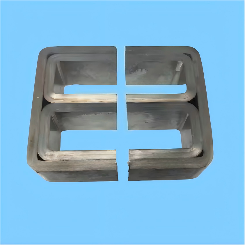
1K101 E shape for bobbin-wound transformers and gapped inductors, with loss published at 20 kHz rather than 50 Hz.
View Details →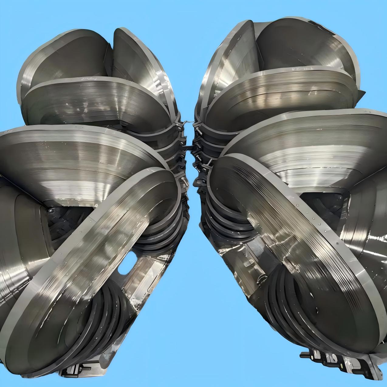
Three-phase symmetrical wound core, 100–2000 kVA, when magnetic balance matters more than a flat SCBH window.
View Details →AMDT cores offer 60-80% lower no-load loss compared to traditional silicon steel transformers, significantly improving energy efficiency and reducing operating costs.
Our AMDT cores can operate reliably at 130°C for long-term applications, with excellent thermal stability and performance consistency.
We offer AMDT cores covering capacities from 30kVA to 2000kVA, with standard dimensions and custom options available.
Yes, we offer comprehensive customization services for special dimension requirements and performance specifications based on your specific design drawings.
Contact our technical experts to discuss how our AMDT cores can help you achieve carbon neutrality goals and create more value for society.