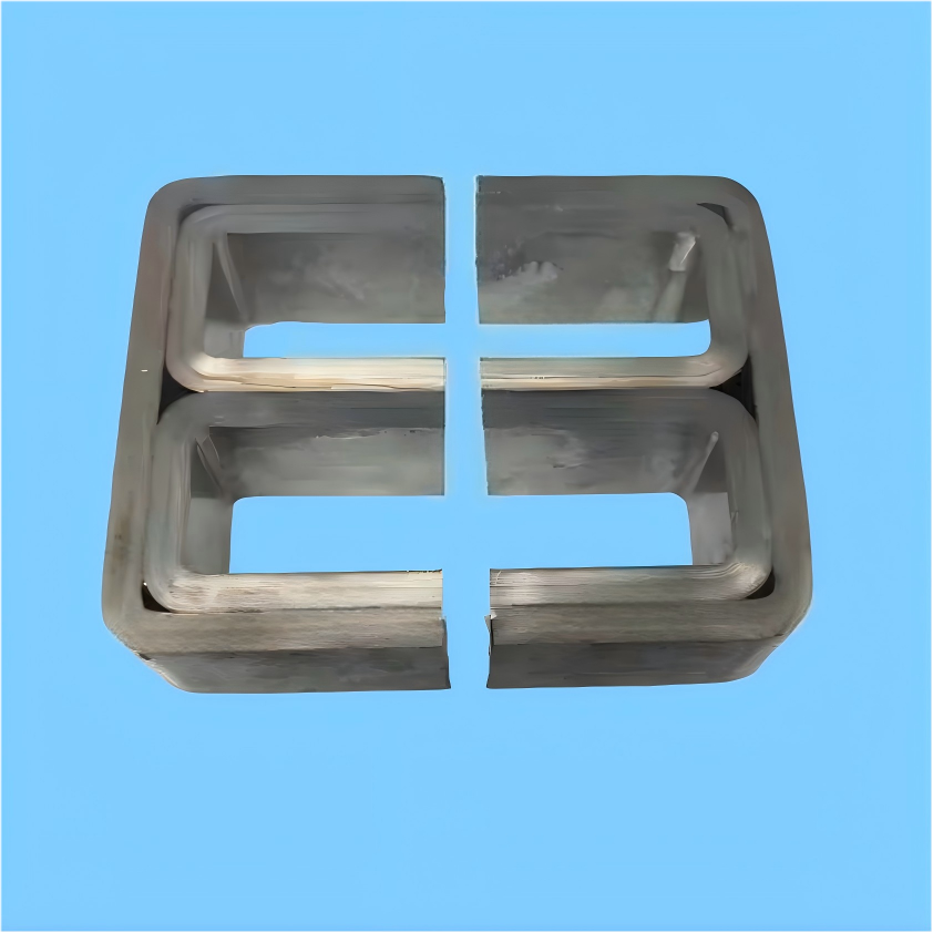
The MagComponent amorphous E-core is the JHAE series, cut from 1K101 iron-based amorphous ribbon into an E so a bobbin can be wound and an air gap can be cut. Saturation flux density is 1.56 T. The loss figure published for this shape is 20–50 W/kg at 20 kHz and 0.2 T, which is a different duty from the 50 Hz planar distribution core made from the same alloy family.
| Parameter | Value | Unit | Conditions |
|---|---|---|---|
| Saturation Flux Density (Bs) | 1.56 | T | H = 800 A/m |
| Curie Temperature (Tc) | 410 | °C | - |
| Resistivity (ρ) | 130 | μΩ·cm | Room Temperature |
| Core Loss (Pcv) | 20-50 | W/kg | @ 20kHz, 0.2T |
| Operating Temperature | -40 to +155 | °C | Standard Range |
Read the 20 kHz row as the signature of this E-core. Core loss is published as 20–50 W/kg at 20 kHz and 0.2 T, and as one fifth to one tenth of silicon steel at the same frequency. Curie temperature on this page is 410°C, resistivity is 130 μΩ·cm, and the operating range is −40°C to +155°C. The amorphous planar core publishes a 50 Hz loss (below 0.15 W/kg at 1.35 T) and a Curie temperature of 415°C. Those are that page's figures for a distribution-transformer geometry, not additional ratings for the E-core.
Choose the amorphous E-core when the part is a single magnetic circuit that will be wound on a bobbin, often with a cut gap, and the frequency of interest is the 20 kHz condition published above. The alloy is 1K101 amorphous ribbon (1.56 T on that page), formed here as the JHAE series rather than as a distribution-transformer window. Ordering on this page is material grade 1K101, series JHAE, with a stated lead time of 2–4 weeks for standard products.
| Selection point | Amorphous E-core (this page) | Amorphous planar core | Nanocrystalline C-core |
|---|---|---|---|
| Shape | E, for bobbin winding, automated winding, and a cut air gap | Flat window for SCBH15/19 dry-type and oil-immersed transformers | Rectangular cut C in nanocrystalline ribbon |
| Published loss or frequency point | 20–50 W/kg at 20 kHz, 0.2 T | < 0.15 W/kg at 50 Hz, 1.35 T | High-frequency transformers and inductors; ribbon thinner than 26 μm |
| Saturation and Curie temperature | 1.56 T, Curie temperature 410°C | 1.56 T, Curie temperature 415°C on that page | 1.2 T, Curie temperature 570°C |
| Operating temperature published | −40°C to +155°C | 130°C long-term on that page | Below 155°C on that page |
| Use it when | A gapped inductor or medium-frequency transformer needs an open E in 1K101 | The specification is a line-frequency distribution transformer and a published kVA window | The design needs the nanocrystalline alloy (1.2 T, 570°C) in a cut C rather than amorphous 1K101 |
Planar and C-core columns repeat values already published on those MagComponent pages. The 3D triangular core is the other amorphous shape to check when the requirement is three-phase symmetry from 100 kVA to 2000 kVA.
The planar AMDT core is a distribution transformer. Its catalog runs from 30 kVA to 2000 kVA dry-type, and its loss is stated at 50 Hz. It does not provide a bobbin leg or a designer-specified gap. If the drawing is an E with a stack height and a gap, stay on this page.
A nanocrystalline C-core is the cut-core alternative in a higher-frequency alloy: 1.2 T and a 570°C Curie temperature, with ribbon under 26 μm. Choose it when that alloy, not 1K101 at the 20 kHz / 0.2 T loss point, is what the design is built on. The E-core's advantage on this page is the open E, the 1.56 T amorphous alloy, and gap cutting to the electromagnetic design.
This page already offers custom air-gap cutting, stack thickness, window size, and overall dimensions, plus coating or casing. Those are geometry options on the JHAE series. They do not change the published 1.56 T, 410°C, or 20–50 W/kg figures, which stay the material and loss statements above.
The common thread is a wound E at the 20 kHz class published above: inverter magnetics, charger inductors, and drive reactors. Vehicle onboard chargers are discussed under EV and electric vehicles. Drive output reactors sit with automation and drives. Solar and wind conversion sit with renewable energy and smart grid. Gap and saturation behavior for a PFC inductor is covered in the PFC inductor saturation case study.
Reactors and transformers in the inverter, where the E can be gapped and the loss point to quote is 20 kHz and 0.2 T. Plant step-up transformers at 50 Hz belong on the planar core page.
PFC inductors and DC/DC transformers that need a bobbin E and a cut gap in 1K101. If the inductor is specified as a 200–600 μi nanocrystalline ribbon instead of an amorphous E, use the low-permeability ribbon page.
High-frequency inductors and transformers inside the UPS. The line-frequency distribution transformer ahead of the UPS is the planar core, not this E.
Output and input reactors for variable-frequency drives and air-conditioning inverters, using the open E and a gap sized to the reactor current.
Medium-frequency transformers and energy-storage inductors whose core loss is judged at the 20 kHz, 0.2 T condition published here, not at 50 Hz.
Converter inductors and transformers in the turbine power stage. The station transformer at line frequency is a planar or 3D triangular core.
Precise magnetic gap cutting according to your electromagnetic design requirements
Customized E-core dimensions including stack thickness, window size, and overall dimensions
Coating or casing options to ensure mechanical strength and insulation performance
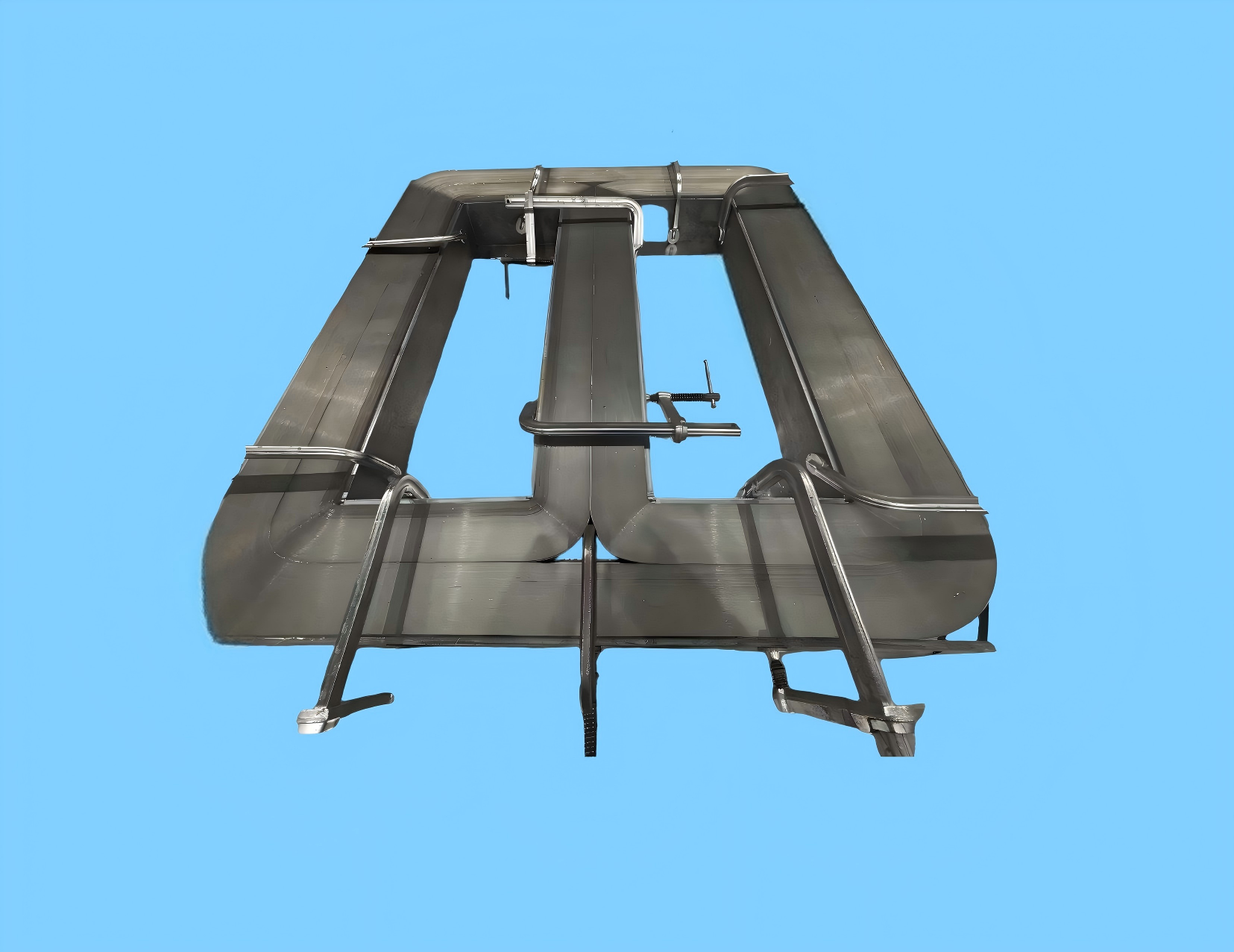
Line-frequency AMDT window for SCBH15/19 transformers, with loss published at 50 Hz rather than 20 kHz.
View Details →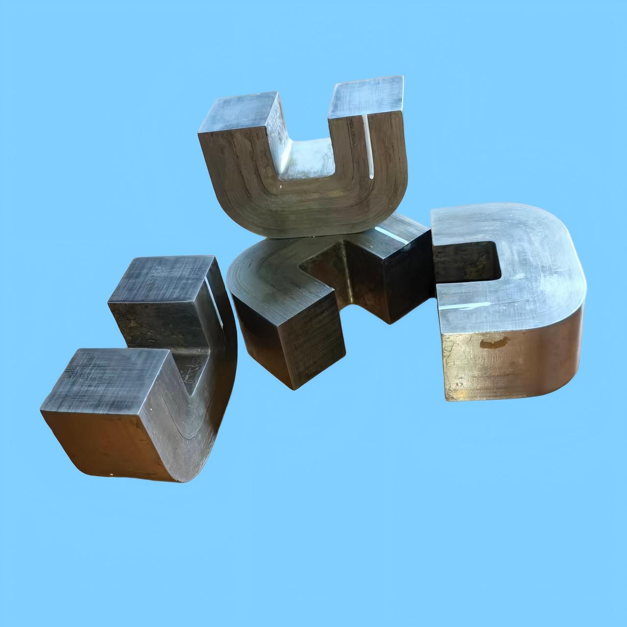
Cut C in nanocrystalline alloy, 1.2 T and 570°C Curie temperature, when the E in 1K101 is the wrong alloy.
View Details →On this page the core loss is one fifth to one tenth of silicon steel at the same frequency, and the loss point published for the E-core is 20–50 W/kg at 20 kHz and 0.2 T. Saturation flux density is 1.56 T. The 1K101 ribbon page lists silicon steel saturation at 1.8–2.0 T, so the E-core is not a higher-saturation part than silicon steel. The published reasons to choose it are the lower loss and the E shape for a medium-frequency winding.
Our 1K101 amorphous E cores can operate reliably from -40°C to +155°C, with a Curie temperature of 410°C, making them suitable for demanding industrial and automotive applications.
Yes, we offer precision cutting services to create custom air gaps and special dimension structures according to your specific electromagnetic design requirements.
We offer both coating (epoxy resin) and casing (plastic or metal housing) finish options to ensure optimal mechanical strength and insulation performance for different application environments.
Contact our technical experts to discuss how our 1K101 amorphous E cores can optimize your high-power applications.